|
What is I2C

Rather than use an 8 bit parallel data bus, the obvious solution was to
use a serial data link. After all, speeds of 1000 bytes/second would be trivial to obtain,
and most people do not change channel that often. A pair of signal lines, Clock and Data
would suffice to link each control system to the central microcontroller. This was nothing
original, however Philips had the idea of a pair of signal lines that linked all the
control systems to the central microcontroller. Then, a protocol was developed which
allowed not only data transmission, but also the addressing of individual control systems,
still only using these 2 lines. In fact, protocol even allows for multiple controlling
microprocessors, but this will not be covered here.

The 2 signal lines, are, as suggested above, Clock and Data. They are
conventionally called SCL and SDA respectively. Both are bi-directional signals,
implemented in the following way : Each device on the I2C
bus can monitor the voltage, or logic level, on both signals. Also, a device may connect
the line to the system ground rail through an electronic switch, or it may leave it
floating (For those who've done a bit of digital electronics, this is known as an `open
collector' output). The first feature provides an input into the device, and the second an
output. External resistors (typically about 4.7k ) are connected between each of the 2
signal lines and the +5V power supply rail, so that if no device on the bus is connecting
a line to ground, then that line appears to be in a logic 1 state. Before the protocol can
be described, it's important to understand 4 terms :
 Transmitter Transmitter
 Receiver Receiver
 Master Master
 Slave Slave
A Transmitter is simply a device that outputs data onto the bus, while a Receiver is
one that accepts data from the bus. Each communication occurs between exactly one
Transmitter and one Receiver.
A Master is the device which controls the SCL line, starts and stops the data transfer,
and controls the addressing of the other devices on the bus.
A Slave is simply the device that has been selected by the Master, and is being controlled
by it.
Again, each communication occurs between exactly one Master and one Slave. There is,
however, no connection between the functions of Master and Slave on the one hand and
Transmitter and Receiver on the other. The I2C driver for
IBM PC's and clones described here is always the Master, but can act as either a
Transmitter or a Receiver, and can therefore communicate in both directions with Slave
devices.
Data Transfer on the I2C Bus
The source code for a Turbo Pascal Unit for an IBM PC to drive the I2C
bus is given in Appendix C. This program should be consulted while reading this
description, even if the final method of implementing the I2C
bus is different.
The most important thing to realise about data transfer on the I2C
bus is that the state of the SDA line can only change when the SCL line is in the logic
low state. The reason for this requirement will be explained later.
The 2 cases of data transfer, either from the Master to the Slave, or from the Slave to
the Master, will now be considered separately.
Transfer from Master to Slave
8-bit bytes are transferred from the Master Transmitter to the Slave Receiver by the
procedure syndi2c in Appendix C. These bytes are sent most-significant bit first, by first
copying the 128s bit of the word into the variable this bit and then setting the SDA line
to the state of this bit. Then the SCL line is pulsed high and low again, to clock that
bit into the Slave device. The low 7 bits of the 8-bit value are now shifted left, so that
each time, the next bit is placed in the 128s bit position. These operations are repeated
for the 8 bits of the byte.
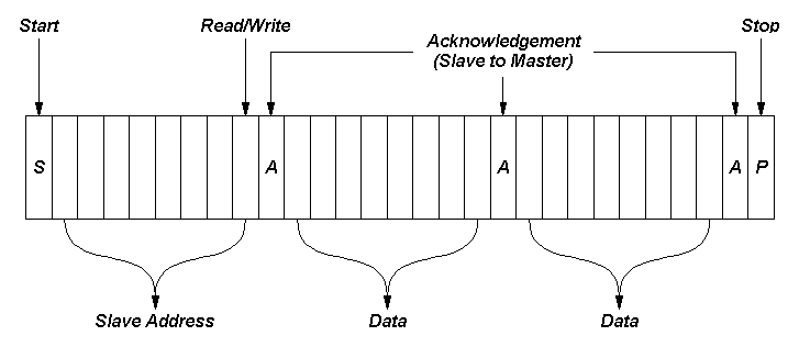
After the 8 bits are transferred, an extra clock pulse is generated, and during this clock
pulse, the state of the SDA line is copied into the ack variable. If the Slave has
accepted the byte, then it will pull the SDA line low during this clock pulse, but if it
hasn't then the SDA line will remain in the logic 1 state. Therefore, if ack is non-zero,
an error has occurred, and the program halts.
Transfer from Slave to Master
8-bit bytes are transferred, most significant bit first, from the Slave Transmitter and
are received at the Master Receiver by the procedure readi2c. This procedure first sets
SDA high (i.e. it turns off the electronic switch connecting SDA to ground), so that the
slave device can control the SDA signal. It then pulses SCL high, shifts the received bits
on the SDA line into the thisbyte variable, and pulls SCL low again. This process is
repeated for the 8 data bits. Finally, a ninth clock pulse is generated for the
acknowledge signal, and if the acknowledge parameter is set to true, then the SDA line is
forced into the logic 0 state, so as to send an acknowledge bit. The I2C
protocol requires that all bytes except for the last are acknowledged. The reason that the
last byte is not acknowledged is to indicate to the Slave that the transfer has finished
and that the Master now requires control of the bus to send a Stop condition.
I2C Bus Control and Addressing
The transfer methods that have been described so far are a relatively standard serial
communication link. The special feature of the I2C bus
lies in the way data transfers over the bus are controlled, and devices are addressed
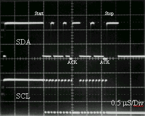
Start and Stop Conditions. Earlier it was stated that during a data transfer, the SDA
signal could only change state while SCL was low. The reason for this is that the protocol
defines 2 special conditions to start and stop communications over the bus as follows :
A Start condition is defined as a change of SDA from logic 1 to logic 0 while SCL is high.
This is performed by the procedure starti2c in Appendix C. This procedure simply ensure
that the SCL line is high (as it would be when the bus is idle), and then pulls SDA low.
Finally SCL is pulled low so that SDA can change state without causing a special
condition.
A Stop condition is defined as a change of SDA from logic 0 to logic 1 while SCL is high.
In appendix C, procedure stopi2c performs this operation, by controlling the signal lines
in the obvious way.
Addressing
Devices on the I2C bus are selected by an 8-bit
address which is sent over the bus in the same way as data bytes. The least significant
bit of this address acts as a read/write control signal, and is set to 0 to make the Slave
a Receiver and 1 to make the Slave a Transmitter.
The address byte is the first byte transmitted after a Start condition. It is always
transmitted by the Master. By convention, if the Slave is a Receiver and the Slave
contains several registers, then the next byte transmitted after the address is an
internal register address for the device. However, this is not required by the I2C specification.
The address of a particular slave device is often determined when the I2C
is manufactured. For example, the SAA5246 Teletext IC that is described below is always at
address 34. Some other devices have a limited number of address inputs which are compared
with certain bits of the received address before the device is selected. The PCD8574 I/O
port is one such device. It has 3 address inputs, while the top 4 bits of the address are
fixed at 0100 binary. Therefore this device can respond to addresses between 64 and 78
A slave device that is selected by a particular address must acknowledge the receipt of
the address byte, while one that is not selected must not. Therefore, it is possible for
the master to determine whether or not a particular slave is present on the I2C bus, which can be useful if certain devices are optional
fitments.
Implementing the I2C Bus
The I2C bus is patented by Philips. However, they
grant certain rights under that patent to purchasers of their devices, or other
manufacturers' devices licensed by Philips. It is normally accepted that provided one
device in every transfer is licensed by Philips, then the other device may be, for
example, a software implementation of the protocol. In other words, using the driver
program in Appendix C to control an Philips SAA5246 Teletext IC is within the terms of the
licence, while implementing the slave functions in software and then using the I2C bus to communicate between 2 PCs would not be.
Microcontrollers with built-in I2C ports
Certain Philips microcontrollers, for example the PCB80C552, have the necessary
hardware on-chip to implement the I2C bus. The program on
the microcontroller simply sends 8-bit bytes to the control and data registers of the
interface hardware, much like using the UART chip of a PC's COM port. While this solution
is sensible if a complete control system is being designed, it is not a useful method to
add the I2C bus to a personal computer system.
The PCD8584 device
The Philips PCD8584 is a device that can be connected to the 8 bit data bus of a
microprocessor, together with the bus control lines, and which provides a similar hardware
interface to the I2C bus as that built-in to the
microcontrollers described above. Although this IC is a powerful and versatile means of
providing I2C communications for a personal computer
system, it is not totally trivial to use.
Parallel Port I2C Implementation
There is nothing that requires that the voltage sensor on each signal line and the
electronic switch to connect the line to ground are part of the same device, provided that
they are both accessible to the control processor. On an IBM PC or clone, the printer port
makes an ideal place to obtain these signals. With a special cable it is then possible to
receive and generate I2C signals.
|
