|
What is Teletext
 |
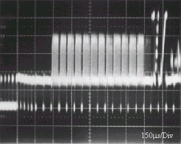 |
Figure 1 - BBC1 2 Fields of Bill Clinton Walking down the
Step of the White House
|
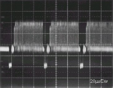
Figure 2 - 12 Teletext lines in the field blanking
interval |
 |
| Figure 3 - BBC1 Teletext Line at 4-JUN-1995 17:18:08 |
Teletext is transmitted during the unused lines of a
Television picture, which may be seen at the top of the picture of a television operating
with reduced height. The signal, if seen look like a series of white small dots that
flicker as each field is scanned. Each line is capable of transmitting 40 useful bytes of
data, another 5 bytes are used for synchronising the clock of the receiver.
The time at which the teletext information is transmitted is called the blanking interval.
This is an interval that is unused due to the problem of depleting the stored emf within
the scan coils. This will be discussed further within this report.
The television picture transmitted here in the UK is interlaced, this means that for a
complete picture to be displayed there has to be two fields, this is for the odd and even
lines that make up the picture. Two fields can be seen in figure 1, 2 fields make one
frame. At the beginning of every field there are the teletext data lines, this can be seen
in figure 2 and an example of the teletext line can be seen in figure 3.
Teletext is becoming a viable method of distributing data from one point to multiple
points with relatively cheap receivers.
Teletext arose because of a historical accident. When Alan Blumlein layed down the
standards for electronically scanned television in the 1930's, he decided to have a
relatively long vertical flyback time - the time it takes for the electron beam to return
from the bottom of the screen to the top after the picture had been scanned. This was
because the electron beam was deflected, as it is today, by an electromagnet, and a rapid
change in the current through this magnet would induce a large back EMF in it. Blumlein
was worried that this high voltage would arc through the glass of the cathode ray tube,
and make a hole in it.
During the vertical flyback time, obviously no picture information could
be transmitted. It was a waste of transmission time. This time was eventually put to a
variety of uses. Engineering test signals were added to the signal to check the
performance of the broadcast television equipment. Then, in October 1972, the BBC
announced the idea of a system of Text screens, which could be selected by the viewer, and
displayed on the television screen. In September 1974, the Teletext service (as it became
known) was started as an experimental service. The standard, however, is almost unchanged
today, although several so-called Extension Packets have been defined.
The teletext line consists of a row of characters. In the European version
of teletext, there are 40 characters per line. These characters occupy an area of 40
centre of the 52 active video region of the teletext line. There are two 6 borders on each
side of the character block. As there are 40 characters per 40 , each character occupies 1
.
The rows of the teletext picture are transmitted sequentially. This means that the time
needed to transmit and therefore display a teletext page is dependent on the number of
teletext lines transmitted with every field of the television signal. The teletext page is
24 rows in height. It uses the centre 240 lines of the screen. Each row is ten lines high
on the television screen. This is why it is more reminiscent of a home computer chunky
graphics display than an ordinary television picture. The display technology of the home
computer is similar in structure and this similarity is utilised by some of the teletext
services. Datacast lines are not used by ordinary teletext decoders but it would not be
impossible to receive these lines. These services, how they are received and their
relative security are covered in a later section dealing specifically with "BBC
Datacasting".
| Bytes in Header and Display Teletext Line |
|
1-2 |
3 |
4-5 |
6-7 |
8-11 |
12-13 |
14-45 |
| Header |
CRI
10101010 |
Framing
11100100 |
Magazine & Row
Address |
Page Number |
Time |
Control Group |
Display Data |
| Display Line |
CRI
10101010 |
Framing
11100100 |
Magazine & Row
Address |
|
Display |
Data |
|
|
|
|
|
|
|
|
|
The first two bytes in each line are 10101010. This format is known as a Clock Run In,
CRI. They synchronise the system clock to the data rate of the teletext data. The
frequency of these bytes is 6.9375 MHz. The lock up of the system clock with the data is
essential.
The third byte is the framing code, 11100100. The purpose of this code is to allow the
decoder to recognise the beginning and end of each byte of data.
The fourth and fifth bytes are the magazine and row address codes. These codes are used to
ensure that the rows of each page of teletext are displayed in the correct order on the
television screen.
From this byte onwards the Display line carries only display data
The sixth & seventh byte carries the page number.
The eighth to the eleventh bytes contain information about timed teletext pages.
The twelfth and thirteenth bytes are the control Group
The fourteenth byte onwards contains display data.
Video Signal Width (64µS-12.05µS-2*6µS) = 40µS
The number of bits transmitted per line = 360
Data Pulse Width = = 111nS
Transmitted Bit Rate = 444 * Line Frequency
Line Frequency = = 15.625 Hz
Burst Bit Rate = = 6.9375 Mbit/s
The Data rate is actually a burst rate, meaning that when data are being
transmitted, they go at that speed, but because there are also moments when no data are
being transmitted, the effective data rate is considerably less.
The transmitted waveform for a teletext line is shown in figure 10. It can be seen that
the peak-to-peak voltage is 0% to 66% video modulation.
Teletext Transmissions
Data Pulse Train
Figure 11 - A NRZ Formatted Byte
The transmission used by teletext is a NRZ (Non-Return to Zero) signal,
with suitably phase corrected shaping filters is as shown in the figure 12. This also
reduces the intersymbol interference as there is minimal energy above 5MHz.
Figure 12 - Data Pulse Spectrum
The corresponding one-bit pulse is indicated in figure 13.
Figure 13 - Data Pulse
Teletext Line Format
| Bytes in the Teletext Transmission |
| 2 |
1 |
2 |
2 |
2 |
2 |
2 |
40 |
| Header |
Clock Run-In |
Magazine & Row Address |
Page
Number
Address |
Time
Minutes |
Time
Hours |
Control
Bits |
Display
Characters |
| 10101010 |
11100100 |
|
|
|
|
|
|
|
|
|
|
|
|
|
|
The data line in table 1 comprises of 360 bits which may be considered as 45 eight-bit
bytes. The first three bytes, which have even parity serve to synchronise the bit and byte
recovery operation in the receiver. The remaining 42 bytes have odd parity and carry
address and control information. The use of odd parity during the variable part of the
data line ensures that there are never more than 14 bit periods between the data level
transitions in the waveform. This simplifies the recovery of the bit rate clock directly
from the data waveform.
All the address and page control information is transmitted using Hamming Code Bytes to
reduce the possibility of the
wrong character rows being stored in the receiver.
Teletext Packet Breakdown
| Packet |
Chapter |
Definitions |
|
|
|
| X/24 |
|
Fastext / Page Extensions |
|
|
|
| X/25 |
|
Telesoftware |
|
|
|
| X/26 |
|
Enhanced Display Facilities and VPT |
|
X/26/0 |
Display Enhancement |
|
|
|
| X/27 |
|
Linked Pages |
|
X/27/0..3 |
Editorial |
|
X/27/4..7 |
Composition |
|
|
|
| X/28 |
|
Page Related Redefinition |
|
X/28/0 |
Data Designations & Colour Def |
|
X/28/1 |
Character Set Designation |
|
X/28/2 |
Conditional Access |
|
|
|
| X/29 |
|
Magazine Related Redefinition |
|
X/29/0 |
Colour Redefinition |
|
X/29/1 |
Character Set Designation |
|
X/29/4 |
|
|
|
|
| 8/30 |
|
Broadcasting Service Data Packet / PDC |
|
8/30/0 |
PDC - Unified Date & Time |
|
8/30/1 |
PDC - Unified Date & Time |
|
8/30/2 |
VPT - VCR Programming |
|
8/30/3 |
VPT - VCR Programming |
|
8/30/4-30/15 |
|
|
|
|
| /31 |
|
Independent Data Line |
|
|
|
iTc Line Definitions
| Line |
Description |
Line |
Description |
| 6 |
Not Used |
318-319 |
|
| 7-9 |
Commercial Teletext Licence |
320-322 |
Commercial Licence |
| 10-17 |
Public Teletext Service Licence |
323-329 |
Public Teletext Service Licence |
| 18 |
Programme Related Teletext |
330-331 |
Programme Related Teletext |
| 19-20 |
Television Test Signals |
332-333 |
Television Test Signals |
| 21 |
Schedule Information (Internal Use) |
334 |
Schedule Information (Internal Use) |
| 22 |
Quiet Line |
335 |
Programme Subtitles |
| 23 |
First Line of Field 1 Television Picture |
336 |
First Line of Field 1 Television Picture |
|
|
|
|
Teletext Levels
| Teletext Level |
Description |
| 1 |
The Initial specifications
set out by the BBC, IBA, BREMA in September 1976 permitting the production of domestic
television sets with Teletext. The specification continued to be developed as additional
features became available. |
| 2 |
Provided Multi-language
text, and a wider range of display attributes that may be non-spacing. There is a wider
range of colours and an extended mosaic pictorial set. |
| 3 |
Introduced dynamically
redefined character sets (DRCS) permitting the display of non-Roman characters, for
example Arabic or Chinese. Pictorial Graphic characters may also be defined, allowing the
composition of improved illustrations for the text compared with earlier versions. |
| 4 |
Includes full geometric
graphics, and requires computing power to generate the display from a sequence of drawing
instructions. This permits graphic displays as good as the highest resolution mode of the
BBC-B computer. This level offers a colour palette of over 250,000 shades. |
| 5 |
Is Full-definition still
pictures, permitting an image of a better quality than achievable from a video camera. It
has no losses due to modulating onto a carrier, and no noise added to the picture during
transmission. |
|
|
Levels 4 & 5 exist as specifications although level 4 was transmitted by the IBA as
long ago as 1981. There appears to be no television sets able to handle these levels, and
until the editors of CEEFAX etc. use it, the extra cost would not be worth while.
Currently Transmitted Level
The currently transmitted level is Level 1. Teletext Ltd (Main independent Teletext
Transmitter) has plans to introduce a Level 2 service from Autumn 1995. After the new
Level 2.5 & 3.5 specifications have been set.
An Early Experimental Mullard decoder utilising TTL technology
Teletext Character Set
|
